-
Wiring
- Pinouts
- Bus Termination Hardware
- Block Diagram
- PCB Design Firmware
- Base Firmware Serial API
- Bluetooth LE Firmware
- Main Firmware App
- Source Code
- Download Legacy
- Beta Hardware Support
- Getting Help
- Troubleshooting
The CAN Bus spec requires a 120Ω resistor between each side of the bus pair. The CANBus Triple has these termination resistors on board, but are disabled by default.
http://en.wikipedia.org/wiki/CAN_bus#Layers
When to enable termination resistors
When attaching the CANBus Triple to an active CAN Bus termination is not required. The bus you connect to is most likely already terminated on each end.
When using the CANBus Triple to MATM (Man in the middle) a bus you will need to enable the termination resistors. This is due to the fact that when you cut the bus to wire the CBT in the middle you would be leaving only one resistor on each end of the bus.
When physically separating a bus you can easily test it for proper termination. Using a Multimeter test the resistance between the CAN High and CAN Low lines. If it reads ~60ohms it has two termination resistors, if it reads ~120ohms it has only one termination resistor.
A properly configured bus looks like this diagram:
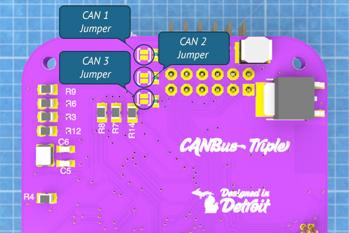
Termination Jumpers
Based on your setup you can activate the termination resistors by adding a dab of solder to the jumper pads shown below. These jumper pads are easily accessible by simply removing the bottom silicone cap.


