Menu
-
Wiring
- Pinouts
- Bus Termination Hardware
- Block Diagram
- PCB Design Firmware
- Base Firmware Serial API
- Bluetooth LE Firmware
- Main Firmware App
- Source Code
- Download Legacy
- Beta Hardware Support
- Getting Help
- Troubleshooting
Main Header

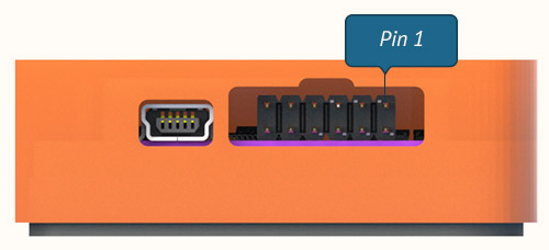
| Pin | Function | Notes |
|---|---|---|
| 1 | Ground | |
| 2 | VDC | Max +16VDC |
| 3 | CAN1 High | |
| 4 | CAN1 Low | |
| 5 | CAN2 High | |
| 6 | CAN2 Low | |
| 7 | CAN3 High | |
| 8 | CAN3 Low | |
| 9 | Analog 0 | Arduino A0 |
| 10 | Analog 1 | Arduino A1 |
| 11 | Analog 4 | Arduino A4 |
| 12 | Analog 5 | Arduino A5 |
Expansion Port
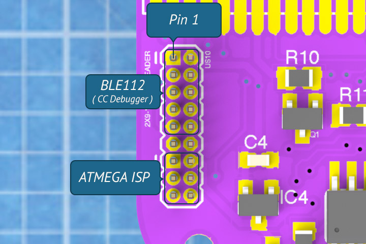
The Expansion port is a 1.27mm 2x9 header. It holds a standard AVR ISP pin configuration, the CC Debugger default pin configuration. It also holds one digital IO from the AVR, and one digital IO from the BLE112 to be used as chip select lines. This enables expansion over SPI for SRAM chips for example.
The expansion port also doubles as a convenient way to flash the BLE112 (via TI CC Debugger) or AVR chip (via ISP Programmer.)

| Pin | IC | Function | Notes |
|---|---|---|---|
| 1 | GND | Ground | |
| 2 | BLE112 | Voltage Sense | |
| 3 | BLE112 | DC | |
| 4 | BLE112 | DD | |
| 5 | BLE112 | CSn | Chip Select |
| 6 | BLE112 | SCLK | Clock |
| 7 | BLE112 | RESET | Reset |
| 8 | BLE112 | MOSI | Master Out Slave In |
| 9 | BLE112 | VCC | +3.3 VDC |
| 10 | BLE112 | MISO | Master In Slave Out |
| 11 | NC | No Connection | |
| 12 | ATMEGA | CS | |
| 13 | ATMEGA | MISO | Master In Slave Out |
| 14 | ATMEGA | VCC | +5 VDC |
| 15 | ATMEGA | SCLK | Clock |
| 16 | ATMEGA | MOSI | Master Out Slave In |
| 17 | ATMEGA | RESET | Reset MCU |
| 18 | GND | Ground |
