-
Wiring
- Pinouts
- Bus Termination Hardware
- Block Diagram
- PCB Design Firmware
- Base Firmware Serial API
- Bluetooth LE Firmware
- Main Firmware App
- Source Code
- Download Legacy
- Beta Hardware Support
- Getting Help
- Troubleshooting
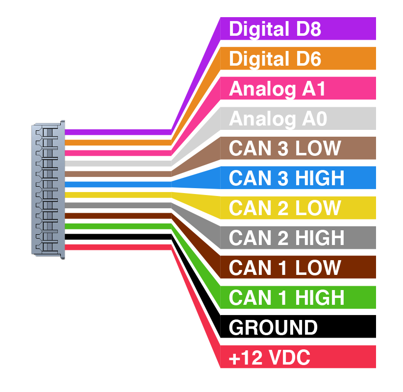
Developer release pinout
Gen 2 MazdaSpeed3 w/ Tech Hardwiring
CAN Connections
You can reach all the required connections by removing the Instrument Panel. It only requires removing two phillips head screws and is the easiest point to tie in that I've found.
Adjust your steering wheel all the way down, and out.
Push up the rubber boot under the IP, attached the the steering column cover. You will find one phillips head screw on the left, and one on the right. Carefully remove them. I suggest using a magnetic screw driver. If you drop the screws you may never find them.
Once those fasteners are out pull the IP toward you and it will unclip from the other dash plastic.
Unclip the wiring harness from the IP by pushing the tab on the top in to release it. Set the IP aside.
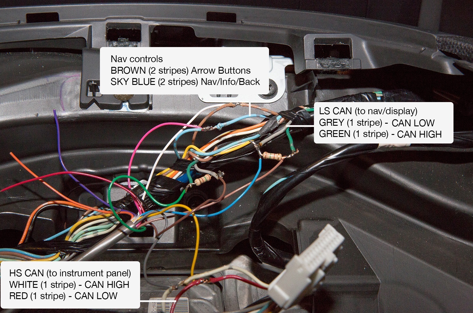
Low speed can connections are first. Clip the Grey and Green wires (1 stripe) and solder in the supplied 120Ω terminating resistors. We're physically separating the CAN bus here, so the spec requires terminating resistors. Wire your CBT developer harness according to the image show here to the left.
The other connections are simple tap-ins. Tap into the High speed can on the IP (Red and White wires) and cover the connections with electrical tape.
Finally, tap into the signals from the wheel buttons. They are the Sky Blue and Brown wires with 2 stripes. Tap in and solder the connections. Cover with electrical tape.
Remove the plastic door for the interior fuse panel near your left knee. Run the harness through the open space toward the fuse panel so you can get power and ground. I used a wire stripper to cut the sheathing, slide it up a bit, and pull out the black and red wires closer to the fuse box.
Instrument panel assembly is simple. Make sure the wires are neatly tucked away. Snap the IP back into place. You may want to use a little masking tape, or gaffer tape to hold the screw on your screw driver. Trust me, you probably will not find the screw if it falls.
CAN Connections
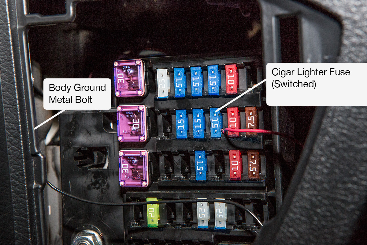
I tapped power from the 'Cigar lighter' fuse. This is the switched one under the climate controls, not the unswitched one in the arm rest. Pull the fuse, wrap the wire around the bottom pole of the fuse and stick it back in.
Get a body ground from the 10mm bolt next to the fuse panel. I stripped off some extra sheathing, wrapped it around the bolt and torqued it back down.
For a nice clean install pop out the OBD-II port by your left knee with your hand or a small screw driver. It has small plastic clips on each side, just push one side and it will pop up and out. Run the CBT wiring harness through the hole. Now you can place your CANBus Triple right there in the little compartment where it's easy to access!
Checkout the code and get hacking!
Base firmware notes from Dev unit
How base firmware works This is a brief overview of how the base firmware functions in its current state. This code is very Beta! It’s been running in daily drivers for over a year, and is considered safe. Functionality is still being added.
The main code sets up the hardware as seen here: These instances of the CANBus library control each bus. It allows us to send and receive CAN packets, read the status of the CAN controller, and more.
CANBus CANBus1(CAN1SELECT, CAN1RESET, 1, "Bus 1");
CANBus CANBus2(CAN2SELECT, CAN2RESET, 2, "Bus 2");
CANBus CANBus3(CAN3SELECT, CAN3RESET, 3, "Bus 3");
Here each bus is initialized. The begin method resets the CAN controller. Then the baud rate is set, and the controller is set to normal operation. The controller will not operate until it is set to normal opperation mode. You can find other modes of operation in the datasheet for the MCP2515 .
// Setup CAN Busses
CANBus1.begin();
CANBus1.baudConfig(125);
CANBus1.setMode(NORMAL);

CANBus2.begin();
CANBus2.baudConfig(500);
CANBus2.setMode(NORMAL);

CANBus3.begin();
CANBus3.baudConfig(125);
CANBus3.setMode(NORMAL);
On to the main loop. Here we process input from the steering wheel buttons. Then we process all the Middleware classes on each incoming CAN packet. More on middleware in the next section.
void loop() {
...
}
Middleware The CAN packets are processed through a Middleware(http://en.wikipedia.org/wiki/Middleware) pattern. This pattern allows developers to easily add and remove functionality to the system. ChannelSwap, MazdaLED, and SerialCommand are Middleware implementations.
To create your own functionality, extend the Middleware Class and add the required processing calls to the main sketch. The processing calls are:
Middleware::process(msg)Here your class can augment the incoming CAN messages.
Middleware::tick()Similar to the main codes loop function, updates time sensitive things. This is not always required, as some implementations may work on just the process method alone. An example of this is the ChannelSwap middleware.
Included Middleware: SerialCommand Takes commands from the serial port. Actual commands will be detailed here soon. The Chrome extension relies on this middleware to get CAN data over the serial port.
MazdaLED Watches for messages to the red screen in the Gen 2 Mazda3 (Probably compatible with the Gen 1 as well). It also listens for sensor data from the High Speed CAN bus to get sensor data from the passive CAN messages. It formats and re-dispatches its own augmented data to display on the red display. If you want to change what shows up on your red display, this is where you start!
ChannelSwap This middleware listens to the CAN busses that are physically separated by the CANBus Triple. It filters and echoes messages between the two busses to ensure functionality on the bus that we’re not augmenting continues to function. In the Mazda3 base firmware this middleware class filters out all messages to the red display, as the MazdaLED class is managing this.
Uploading code The Arduino IDE makes it simple to upload your modified firmware. Just click upload and your code is compiled and uploaded to the CANBus Triple. If you get errors be sure you placed the libraries in your libraries folder located inside your Arduino Sketchbook folder.